








HEPA Filter In-Situ Leak Testing: How Exhaust Filters Are Scan-Tested and Decontaminated in Place
A HEPA filter that passed its factory test can still leak once it is installed: a damaged gasket, a frame that does not sit flat, or a pinhole made during handling lets unfiltered air bypass the media. That is why cleanrooms and biosafety laboratories test filters in place. For exhaust filters in a containment facility this is harder than it sounds, because the side that has to be scanned is inside the duct. This guide explains how installed HEPA filters are leak-tested, why exhaust filters need a purpose-built in-situ test and decontamination housing, and what to specify.
Filter Efficiency Test vs Installed Leak Test
Two different tests are often confused:
- Efficiency (classification) test — done by the filter manufacturer on a test rig, to classify the filter as H13, H14, U15 and so on under EN 1822 or ISO 29463. It proves the media and the filter as built. See HEPA H13 vs H14 for what the classes mean.
- Installed filter leak test — done on site after installation, after every filter change and periodically in service. It checks the whole installed system: media, frame, the seal between filter and housing, and the housing itself. ISO 14644-3 describes the method; IEST-RP-CC034 is a widely used practice document.
Most leaks found on site are not in the media but at the seal — a gasket that has been compressed unevenly, a gel seal knife-edge that is not fully seated, or a gap at a corner of the frame.
How an Installed HEPA Filter Is Scan-Tested
- Challenge aerosol upstream. A test aerosol — typically poly-alpha-olefin (PAO) or a similar oil — is injected into the airstream upstream of the filter and allowed to mix.
- Measure the upstream concentration. The concentration reaching the filter face is measured through an upstream sampling port. This is the 100% reference.
- Scan the downstream face. A probe connected to an aerosol photometer (or a particle counter) is moved slowly across the entire downstream face and around the frame and seal, in overlapping strokes a few centimetres from the surface, commonly at about 5 cm/s.
- Judge leaks. With the photometer method, a reading above 0.01% of the upstream concentration is normally treated as a leak. The spot is then confirmed with the probe held stationary.
- Repair or replace and retest. Seal leaks are corrected by reseating the filter; media leaks mean the filter is replaced. The filter is then retested.
Where the downstream face cannot be scanned, ISO 14644-3 also allows an overall leak test: the downstream concentration is sampled at one point after the air has mixed and compared with the upstream value. It confirms that total penetration is acceptable but cannot locate a leak.
Why Exhaust Filters in Containment Are Different
For a supply filter in a cleanroom ceiling, the downstream face points into the room, so a technician can scan it from below. For an exhaust filter in a BSL-3 laboratory, a negative-pressure suite or a potent-compound area it is the other way round:
- The upstream face (the dirty side) faces the room and collects the hazardous material.
- The downstream face (the clean side) is inside the housing or duct, where nobody can reach it without opening the housing.
Opening the housing to scan it would expose the technician and break containment. China’s biosafety laboratory standards GB 19489 and GB 50346 therefore expect high-containment exhaust HEPA filters to be decontaminated and leak-tested in place, and international guidance for high-containment laboratories takes the same approach. The housing has to bring the test functions to the outside.
What an In-Situ Test and Decontamination Housing Includes
| Function | How it is provided |
|---|---|
| Aerosol challenge | An aerosol injection port upstream of the filter, positioned so the challenge mixes evenly across the face. |
| Upstream reference | An upstream sampling port to measure the 100% concentration. |
| Downstream scan | A scanning probe inside the housing on the clean side, moved across the filter face by a handle or drive outside the housing — either linear scanning or fixed sampling points. |
| Decontamination | A decontamination port and cover so VHP or another gaseous decontaminant can be circulated through the filter before maintenance or change-out. |
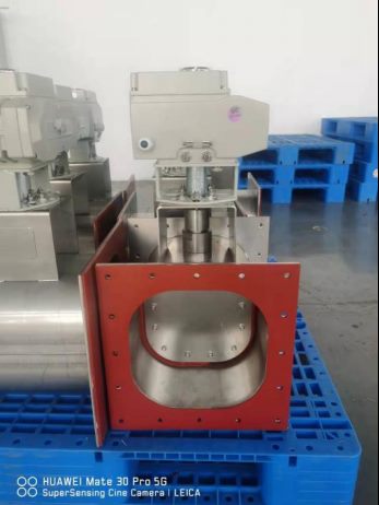
| Isolation | A gas-tight biosafety isolation damper in the duct, so the housing can be sealed during decontamination and filter change. |
| Monitoring | A differential pressure gauge across the filter to show loading and a damaged or bypassed filter. |
| Housing tightness | Fully welded stainless steel body, tested for leak tightness at a stated pressure, so the housing itself is not a leak path. |
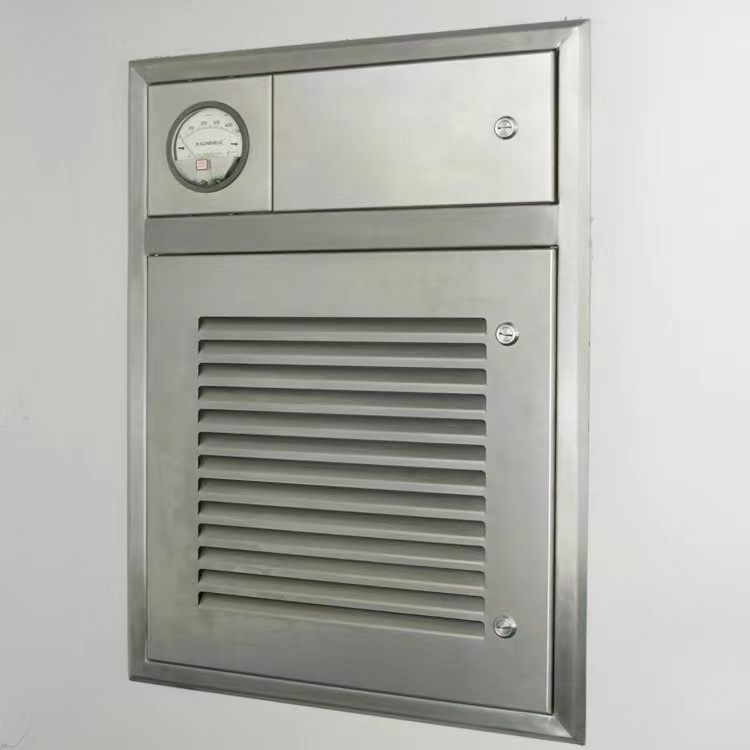
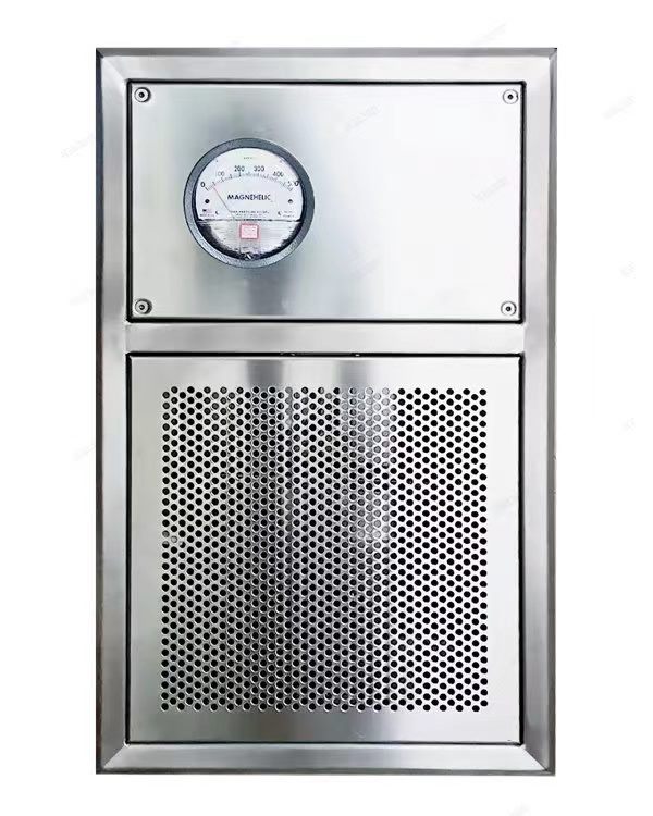
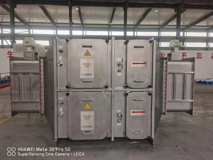
In large exhaust systems the same functions are built into bag-in/bag-out (BIBO) filter housings with a scan section. For room-side exhaust points — at the wall or ceiling of each laboratory — they are packaged into a compact in-situ decontamination exhaust unit (also called an in-situ test exhaust grille, scannable exhaust HEPA box or terminal exhaust filter box).
Decontaminating the Filter in Place
Before an exhaust filter is changed, or before maintenance on the housing, the filter has to be made safe. The usual sequence is:
- Close the isolation damper downstream so the housing is sealed.
- Fit the decontamination cover over the room-side grille and connect a VHP generator — for example a VHP BIBO sterilizer — to the decontamination ports.
- Circulate hydrogen peroxide vapour through the filter media and housing for the validated cycle, using biological indicators to confirm the result. See VHP validation with biological indicators.
- Aerate until residual hydrogen peroxide falls below the set limit, then change the filter and leak test the new installation.
When a whole laboratory is decontaminated, the exhaust filters inside the sealed boundary are treated together with the room by an HVAC-integrated VHP system.
When to Leak Test
- After installation, as part of commissioning and room qualification.
- After every filter change or any work that disturbs the filter seal.
- Periodically in service — in high-containment laboratories this is commonly done at least once a year as part of the annual performance verification.
- Whenever the pressure gauge shows an unexplained drop in pressure difference, which can indicate a bypass.
Design Points to Check
| Item | What to check |
|---|---|
| Test access | All test and decontamination ports grouped in one interface box outside the room; no need to open the housing. |
| Scan coverage | The probe covers the whole filter face and the full seal perimeter. |
| Housing leak tightness | Stated leak rate at a stated test pressure, with a test record. |
| Filter class and seal | H13 or H14; seal type (gasket or gel) and how it is clamped evenly. |
| Airflow and size | Rated airflow per unit matched to the room air change rate; housing size suits the wall or ceiling. |
| Mounting | Ceiling or wall mounting; low-level exhaust for rooms that need it. |
| Materials | Stainless steel resistant to VHP and the disinfectants used. |
Fenggu In-Situ Decontamination Exhaust Unit
The Fenggu In-Situ Decontamination Exhaust Unit (FG-AIR-ISD) is a terminal exhaust HEPA housing for biosafety laboratories, negative-pressure production rooms and hospital isolation areas. It consists of a plenum box, HEPA filter, exhaust grille and control box, with all interfaces — scanning handle, aerosol and test ports, and decontamination port — grouped in one interface box.
| Functions | In-situ decontamination (with decontamination cover) and in-situ scan leak testing of the filter |
|---|---|
| Housing | Stainless steel, fully welded, resistant to acids, alkalis and disinfectants |
| Leak tightness | Leak rate ≤ 0.1% of net volume per minute at ≥ −1,000 Pa (third-party tested) |
| Standard sizes | 250, 500 and 1,000 m³/h, customised sizes available |
| Mounting | Ceiling or side wall |
| Options | Biosafety isolation damper for filter change without system shutdown; perforated, louvred or slotted grille; UV lamp |
For main exhaust ducts with larger airflows, see the BIBO filter housing with in-line scanning.
FAQ
What is an in-situ HEPA filter leak test?
A test carried out on the filter in its installed position: a challenge aerosol is introduced upstream and the downstream side is scanned to find leaks in the media, frame or seal.
What leak is acceptable in a HEPA scan test?
With the aerosol photometer method in ISO 14644-3, a reading above 0.01% of the upstream concentration at any point is normally treated as a leak that must be repaired.
Why can’t exhaust filters be scanned from the room?
Because the room faces the dirty upstream side. The clean downstream side is inside the housing, so the scanning probe has to be built into the housing and operated from outside.
Which aerosol is used?
Poly-alpha-olefin (PAO) is the most common challenge aerosol today; DOP was used in the past. The test equipment and aerosol generator are supplied by the testing contractor or the facility’s own validation team.
How often should exhaust HEPA filters in a BSL-3 lab be tested?
After installation, after every filter change, and periodically in service — commonly at least annually as part of the laboratory’s performance verification.
Related Products
 Safe-Change Exhaust UnitHEPA exhaust terminal decontaminated and leak-scanned in place.Air Handling
 BIBO Filter HousingBag-in/bag-out HEPA housing for safe filter change in P3/P4 labs.Air Handling
 Biosafety Isolation DamperAirtight damper isolating HVAC ducts during decon and BIBO change.Transfer & Containment
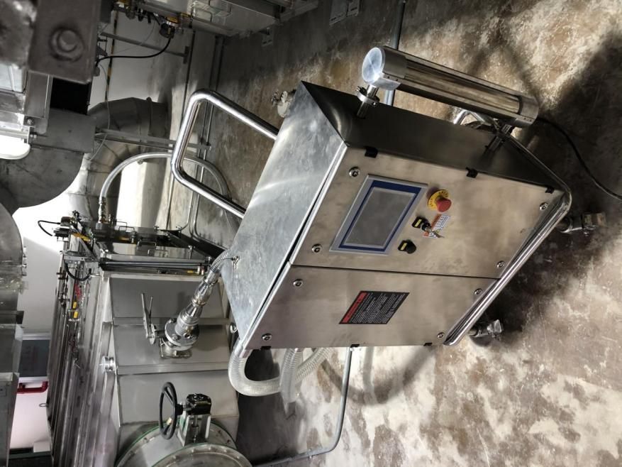 VHP BIBO SterilizerDedicated unit for decontaminating BIBO filter housings.VHP Sterilization
Planning Exhaust Filtration for a Containment Lab?
Send us your room airflow, mounting position and test requirements. Fenggu engineers will size in-situ decontamination exhaust units and isolation dampers for your layout.