








Designing an Integrated VHP System for a BSL-3 Laboratory: 10 Engineering Decisions
An integrated VHP system in a BSL-3 laboratory is not a generator added to a finished room. It has to work with the HVAC system, the room envelope, the pressure cascade, the building management system (BMS), and the pass boxes, biosafety cabinets and exhaust filters. Most problems found at commissioning were decided, or missed, at design stage. This guide covers the ten decisions that designers, contractors and laboratory owners should settle before the drawings are frozen.
Key points
- Define what “integrated” means for the project — whole-suite through the HVAC, local loops, or self-contained equipment cycles — and who owns each interface.
- The core area must stay negative to its surroundings in every phase of the cycle, including start-up and aeration. Exhaust HEPA filters are never bypassed.
- Every surface the vapor touches, down to sealants, gaskets, sensor heads and cable jackets, needs a compatibility check.
- Pass boxes, biosafety cabinets and exhaust HEPA housings need their own decontamination route, not just the room cycle.
- Cycle parameters come from validation, not from a datasheet. Plan worst-case monitoring points and BI locations at design stage.
For how a whole-room cycle is run in an existing laboratory, see BSL-3 laboratory VHP room decontamination. This article is about the design stage.
1. Define the integration boundary and who owns each interface
Start by deciding what the VHP system has to reach and how. The answer sets the equipment, the HVAC modifications and the control logic.
| Approach | What it covers | Typical equipment |
|---|---|---|
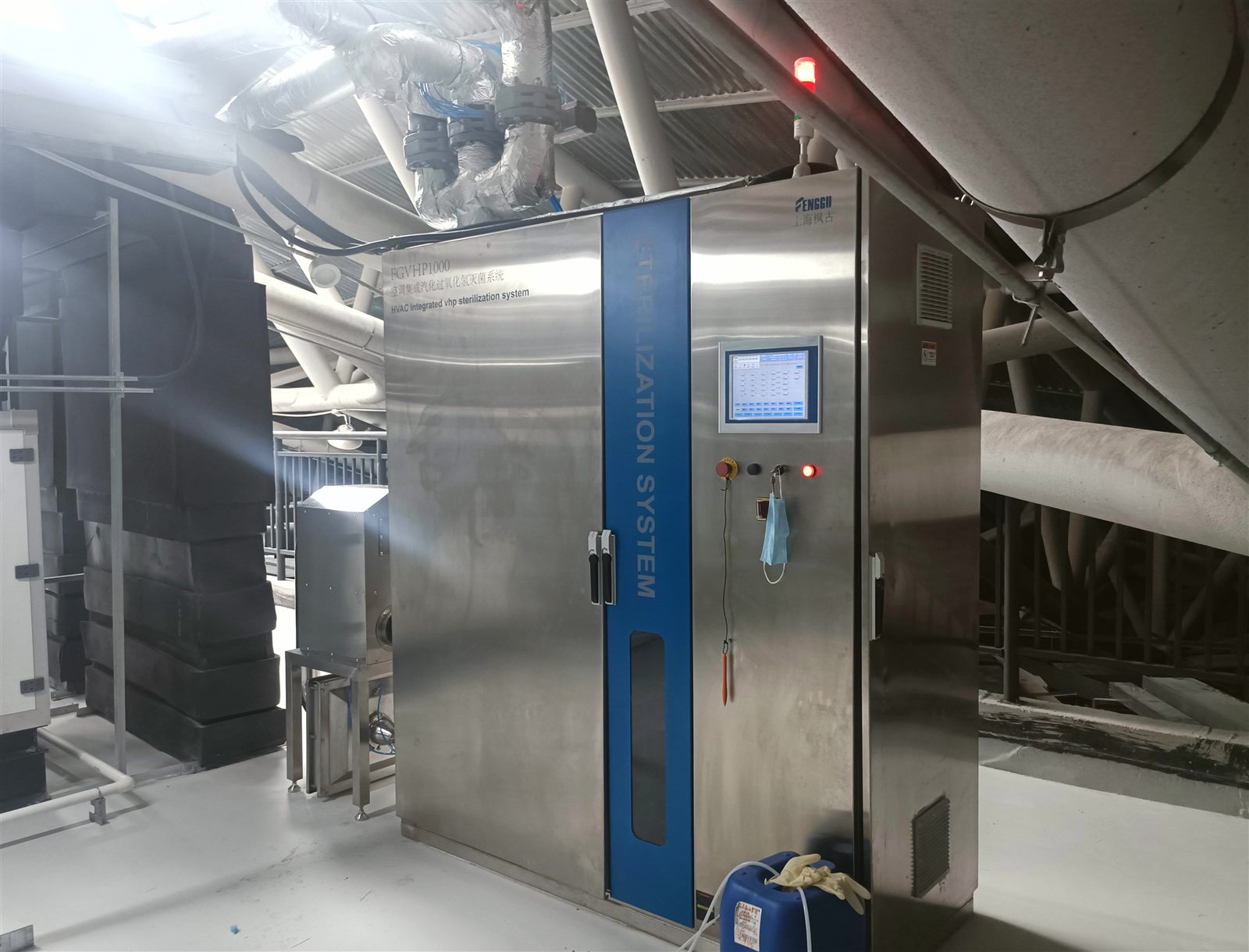
| Whole-suite through the HVAC | Core lab, anterooms and the supply/return ductwork in one cycle | HVAC-integrated VHP system |
| Room by room | One room at a time, isolated from the ductwork by dampers | Mobile VHP generator through wall ports |
| Local loops | Biosafety cabinet interiors, exhaust HEPA housings | Recirculating generator, BIBO sterilizer |
| Self-contained equipment | Materials passing in and out | Pass box with its own cycle |
Most BSL-3 projects combine several of these. List the operating scenarios too: routine decontamination, decontamination before maintenance or filter change, and terminal decontamination after an incident. Then write down the interfaces between the VHP supplier, the HVAC contractor, the BMS integrator, the envelope contractor and the biosafety equipment suppliers. A missing signal or an interlock nobody owned is one of the most common commissioning findings.
2. Keep the pressure cascade in every phase
Directional airflow into the core area is the basis of BSL-3 containment, and a VHP cycle must not interrupt it. The moments to check are cycle start, when dampers move and the generator injects, and aeration, when exhaust is reopened.
- Give the BMS a dedicated decontamination mode that keeps the core area negative and handles alarms correctly during the cycle.
- Sequence supply and exhaust dampers so that the room never goes positive, even briefly.
- For HVAC-level cycles, trace the vapor path and confirm it cannot leak into ceiling voids, service spaces or adjacent rooms.
- Never bypass the exhaust HEPA or BIBO filters to make recirculation easier. Air leaving the containment boundary must always be HEPA-filtered.
- Interlock doors, pass boxes, access hatches and duct valves with the VHP program so they cannot be opened during a cycle.
3. Check material compatibility down to the small parts
Hydrogen peroxide vapor is a strong oxidizer. Repeated exposure accelerates ageing, embrittlement and corrosion, and the failures usually start with small parts.
| Item | Prefer | Avoid or verify |
|---|---|---|
| Room envelope | Stainless steel or panels rated for oxidizing disinfectants; VHP-resistant joint sealant | Untested sealants and coatings |
| Ducts, grilles, valves | Stainless steel | Plain carbon steel, copper, brass, zinc |
| Gaskets and seals | Materials verified for repeated VHP exposure | Unknown elastomers |
| Filters, sensor heads, cable jackets | Supplier-confirmed VHP compatibility | Assuming compatibility |
| Pass box, BSC and BIBO interiors | SUS304/SUS316L, passivated or electropolished | Painted mild steel |
More detail is in VHP material compatibility.
4. Plan injection points, mixing and monitoring points
Efficacy depends on vapor reaching every surface at the target concentration. That is decided by where vapor enters, how air moves and where it is measured.
- Locate injection points, circulation fans and distribution piping so the vapor mixes quickly, and install multiple concentration sensors rather than one.
- High-level supply with low-level exhaust reduces stagnant zones.
- Mark the hard-to-reach locations on the drawings now: duct bends, plenums, the downstream side of dampers, ceiling voids and the space behind large equipment. These become worst-case points in performance qualification.
- Pass boxes benefit from internal circulation fans or baffles so that the load does not shield surfaces.
- Give biosafety cabinets and BIBO housings decontamination ports or a circulation connection.
5. Control humidity, temperature, concentration and aeration in one loop
Temperature, relative humidity, hydrogen peroxide concentration and contact time determine the result. Dehumidification, temperature control, concentration monitoring and aeration should all run under one automated program.
Humidity that is too high causes condensation and corrosion; too low and the kill rate falls. Cold surfaces cause local condensation. Equipment specifications give operating ranges — for example, the Fenggu FG-VHP-C1000 operates at 25–35 °C, below 50% RH and at 150–800 ppm — but the cycle values for a specific laboratory have to be set by cycle development, PQ and the biosafety risk assessment, not copied from a datasheet. See VHP concentration, humidity and condensation.
6. Give pass boxes, cabinets and exhaust filters their own cycles
These are the critical points for contamination control, and a room cycle alone does not prove them.
- Pass boxes: interlocked doors that release only after the cycle and aeration are complete; space between items; no wet loads.
- Biosafety cabinets: a built-in VHP module or an external connection, without compromising the cabinet’s own containment. See biosafety cabinet VHP decontamination.
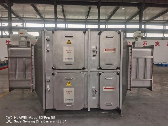
- Exhaust HEPA and BIBO housings: in-place decontamination, with a VHP connection, a scan or test port and room for maintenance.
- Waste and equipment leaving the lab: “decontaminate first, then remove”, enforced by interlocks.
7. Design the safety interlocks and gas detection
- Lock room access during the cycle. An abnormal door status should stop the cycle or move it to a safe state.
- Place hydrogen peroxide detectors where vapor can accumulate, linked to exhaust, audible and visual alarms, and access control.
- Keep entry doors and the clean-side door of the pass box locked until aeration is complete. The common occupational limit is 1 ppm as an 8-hour average.
- Specify audit trail, user levels, data storage and fault logging in the control system.
- Provide for emergency aeration, manual ventilation, a leak response procedure and PPE.
8. Design the validation in, not on
A power-on test is not validation. Plan IQ, OQ and PQ from the start:
| Stage | What it proves |
|---|---|
| IQ | Materials, locations, piping insulation, sensor calibration and interlock logic match the design. |
| OQ | Dehumidification, gassing, aeration, alarms, interlocks and data recording all work. |
| PQ | Concentration distribution and microbial kill under empty, typical and worst-case loads, with biological indicators at the hardest points. |
Keep separate loading patterns and validation files for pass boxes, cabinets, BIBO housings and duct sections. See VHP cycle development and qualification and VHP validation with biological indicators.
9. Plan maintenance and change control before handover
Hand over a cycle SOP, loading lists, a training plan and maintenance procedures. Calibrate concentration, temperature and humidity sensors and alarms on a schedule. Inspect sealants, filters, fans, dampers and pass box seals for ageing. Any change to room layout, loading, HVAC settings or the cycle program needs a risk assessment and, where necessary, requalification. Keep run logs, alarm records, validation reports and maintenance records.
10. Involve the equipment manufacturer at design stage
Treating equipment purchase and system integration as separate jobs is a common mistake. When the VHP manufacturer is involved early, it can provide:
- Footprint, connection positions, power and piping insulation requirements while the plant room is still being laid out. For example, the FG-VHP-C1000 measures 1,800 × 600 × 1,900 mm and the C2000 2,400 × 600 × 1,900 mm.
- Suggested injection and sensor positions based on room volumes and loads.
- Cycle templates and loading guidance for pass boxes, BIBO housings and other equipment.
- Commissioning, BI validation support, maintenance and operator training.
A joint design review by the equipment manufacturer, the engineering contractor, the laboratory and the validation team before construction catches most interface problems while they are still cheap to fix.
Design review checklist
| Decision | Question to close at design stage |
|---|---|
| Boundary | Which rooms, ducts and equipment are in scope, by which method, and who owns each interface? |
| Pressure | Does the BMS decontamination mode keep the core negative at start-up and during aeration? |
| Materials | Are sealants, gaskets, sensors and cable jackets confirmed VHP-compatible? |
| Distribution | Where are the injection points, fans, sensors and worst-case locations? |
| Control | Are humidity, temperature, concentration and aeration under one program? |
| Critical equipment | How are pass boxes, cabinets and exhaust filters decontaminated? |
| Interlocks | Which doors, hatches and valves are locked, and what happens on a fault? |
| Validation | Are IQ/OQ/PQ, BI positions and worst-case loads defined? |
| Operation | Who maintains sensors and seals, and what triggers requalification? |
| Team | Has the manufacturer reviewed the drawings with the contractor and the laboratory? |
Fenggu Equipment for This
- HVAC-integrated VHP system (FG-VHP-C1000 / C2000) — treats a suite and its ductwork through the existing air-handling plant.
- Mobile VHP room sterilizer (FG-VHP-M500) — for room-by-room cycles up to 300 m³.
- VHP BIBO sterilizer (FG-VHP-BIBO) — in-place decontamination of BIBO HEPA housings before a filter change.
- Safe-change exhaust unit (FG-AIR-ISD) — HEPA exhaust terminal that can be decontaminated and leak-scanned in place.
- Biosafety isolation damper (FG-LOCK-BCV) — seals supply and exhaust ducts during room decontamination.
- Inflatable-seal airtight door (FG-LOCK-GDI) — for containment and decontamination rooms.
- Biosafety pass box (FG-PB-BIO) — mechanically sealed, gas-decontaminatable transfer chamber for BSL-2/3 laboratories.
All VHP equipment: VHP sterilizers and generators.
FAQ
What is an integrated VHP system in a BSL-3 laboratory?
A VHP system designed together with the HVAC, room envelope, BMS and biosafety equipment, so that rooms, ducts and critical equipment can be decontaminated without breaking containment. It may be one HVAC-level system or a combination of HVAC, mobile and equipment-level cycles.
Can the exhaust HEPA filters be bypassed during a VHP cycle?
No. Air leaving the containment boundary must pass through the exhaust HEPA filters at all times. Recirculation has to be designed around them.
Does the laboratory have to stay under negative pressure during VHP decontamination?
Yes. The core area must stay negative to adjacent areas during every phase, including start-up and aeration. This needs a dedicated BMS mode and careful damper sequencing.
What concentration and humidity should a BSL-3 VHP cycle use?
There is no universal value. Equipment has operating ranges, but the cycle for a given laboratory is set by cycle development and confirmed in PQ with biological indicators at worst-case locations.
When should the VHP equipment supplier be involved?
At design stage, before the plant room, ductwork and control philosophy are fixed. Footprint, connections, injection points and interlocks are much harder to change after construction.
References
- WHO Laboratory Biosafety Manual, 4th edition (2020)
- CDC/NIH, Biosafety in Microbiological and Biomedical Laboratories (BMBL), 6th edition (2020)
- GB 19489-2008, Laboratories — General requirements for biosafety
- GB 50346-2011, Architectural and technical code for biosafety laboratories
- EN 17272:2020, Methods of airborne room disinfection by automated process
- OSHA 29 CFR 1910.1000, Table Z-1 — hydrogen peroxide PEL 1 ppm (8-hour TWA)
Related Products
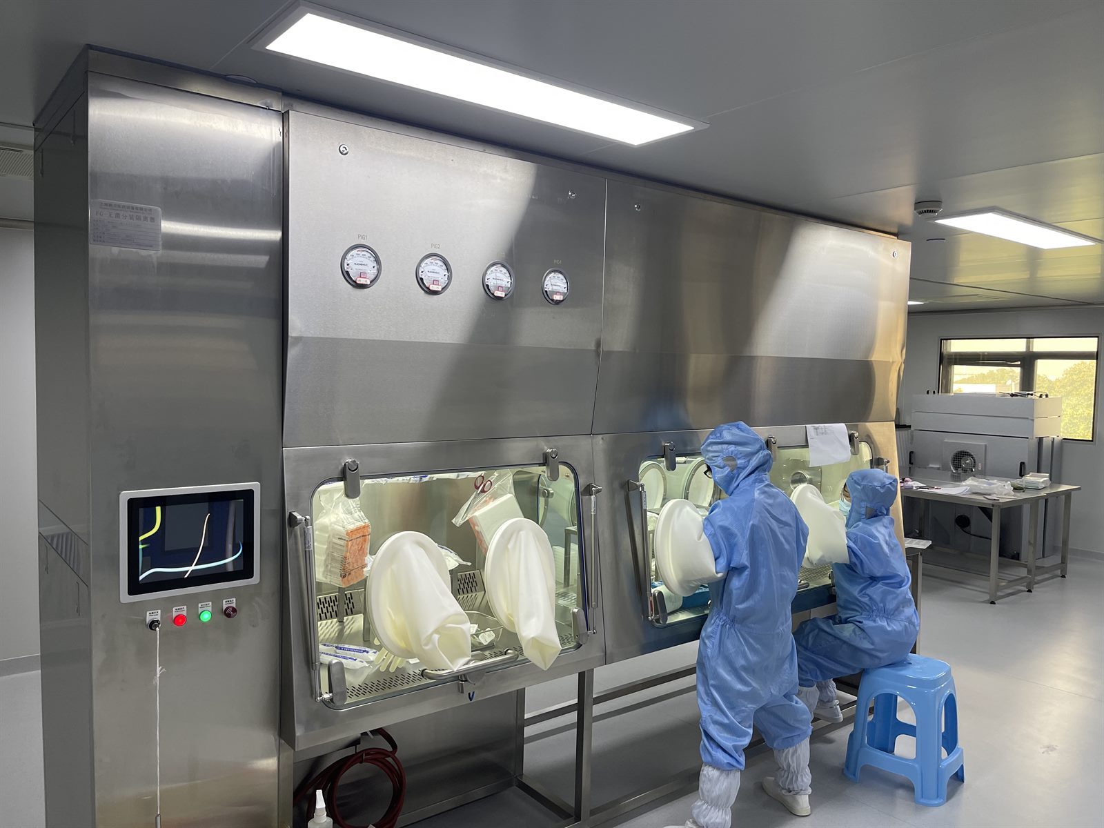 Aseptic Filling IsolatorGrade A (ISO 5) barrier for sterile filling, stoppering and capping.Isolators & Barrier
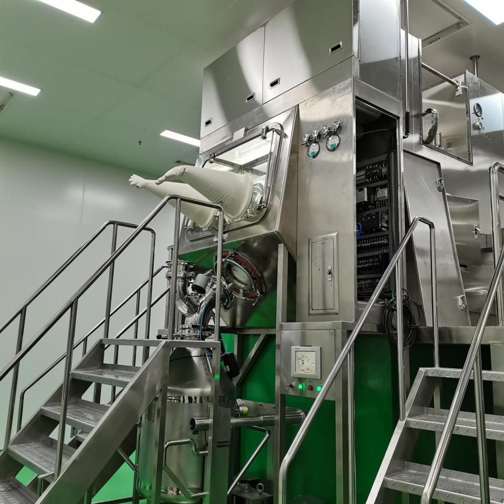 Dispensing & Containment Isolator (OEB5)Negative-pressure barrier for weighing, charging and sampling HPAPI.Isolators & Barrier
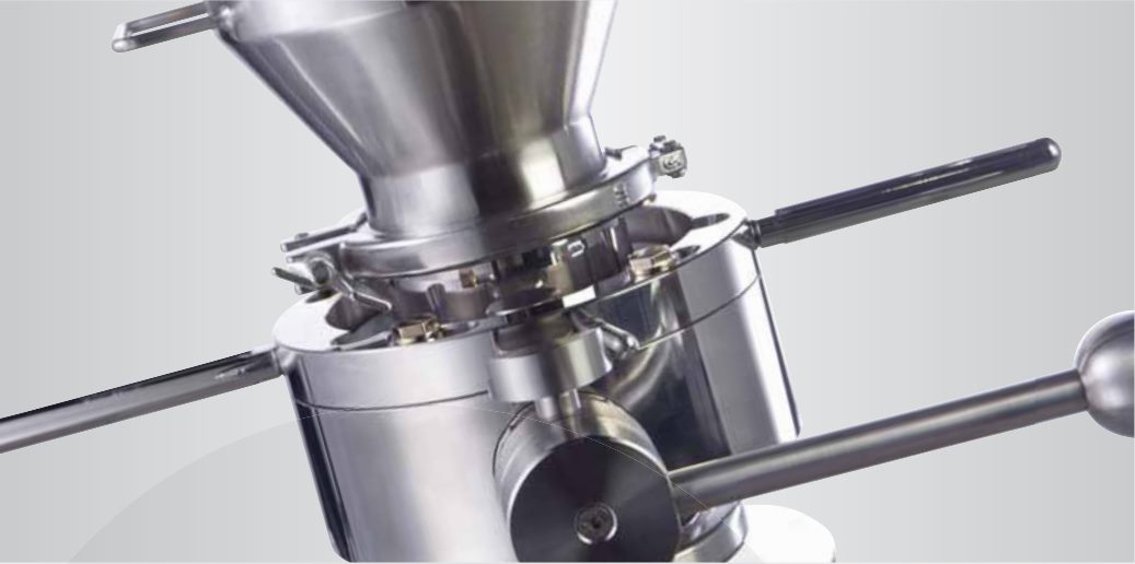 Alpha-Beta Split Butterfly ValveSplit butterfly valve for contained, dust-free transfer of potent powders.Transfer & Containment
 BIBO Filter HousingBag-in/bag-out HEPA housing for safe filter change in P3/P4 labs.Air Handling
Designing a BSL-3 Laboratory with VHP?
Send the layout, HVAC schematic and list of cabinets and filter housings. Our engineers will review the integration points and propose the equipment.