








Reactor Charging Isolators: How to Specify an Isolator for Your Reactor Manway
Charging a reactor through an open manway is one of the highest-exposure steps in API and HPAPI production: bags are cut, powder falls a long way, solvent vapour rises from the vessel and dust follows the operator out of the room. A reactor charging isolator — also called a reactor feeding isolator, manway charging isolator, charging glovebox or, in some supplier catalogues, an MDS isolator — closes that step. This guide covers what the isolator is made of, the design questions that are specific to reactors, a specification checklist, and how the unit is tested before it goes into service.
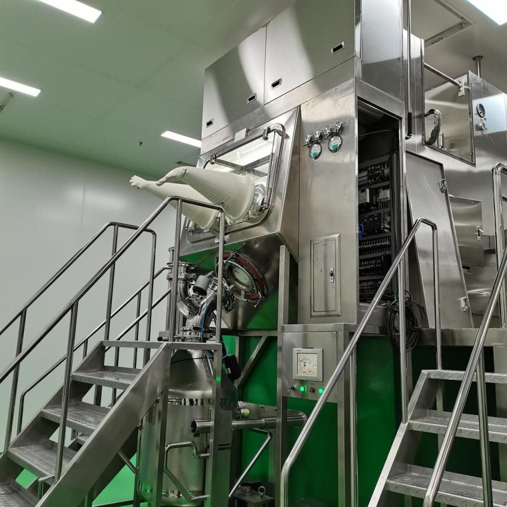
If you are still deciding how to charge — isolator, vacuum conveying, FIBC docking or split valves — start with our overview of contained reactor charging methods. This article assumes you have chosen an isolator and need to specify one.
What a Reactor Charging Isolator Is
It is a negative-pressure containment isolator built to sit on the reactor manway (or a dedicated charging nozzle). The operator brings sealed bags or containers into the chamber, opens and empties them through the glove ports, and the powder drops through a chute into the reactor. The isolator protects the operator and the room from the product; unlike an aseptic isolator, it does not protect the product from the operator.
Two things make it different from a general OEB4/OEB5 containment isolator used for weighing or sampling:
- It is connected to a process vessel. The reactor may contain warm solvent, be under nitrogen, or be at a small positive or negative pressure. The isolator is a low-pressure enclosure and must never be exposed to reactor pressure.
- It is often in a flammable atmosphere. Solvent vapour from the reactor plus fine organic powder can form an explosive mixture inside the chamber.
Anatomy of a Charging Isolator
| Component | What it does |
|---|---|
| Chamber and glove ports | Welded stainless steel shell with a viewing window and glove ports at working height. The number and position of gloves follow the bag size and how the operator lifts, cuts and shakes it. |
| Material entry | Bags or liners enter through a bag-in port or a pass-through chamber; drums and IBCs can dock through a rapid transfer port (RTP) or a split butterfly valve. |
| Bag cutting grid | A grid or sieve over the chute where bags are opened and emptied. It also stops bag fragments and lumps from entering the reactor. |
| Discharge chute | A steep, smooth chute from the chamber floor to the reactor nozzle, sized so powder does not bridge. |
| Isolation valve | A valve between the chute and the reactor, closed except while charging. It separates the isolator from reactor pressure and vapour and allows the isolator to be cleaned while the reactor runs. |
| HEPA supply and exhaust | Filtered air in, filtered air out to the exhaust fan. Exhaust filters are usually changed through the gloves (push-push) so the operator is not exposed during the change. |
| Pressure control | Keeps the chamber negative to the room and alarms on loss of negative pressure. |
| Nitrogen purge | For flammable solvents, the chamber is inerted with nitrogen and oxygen is monitored before charging begins. |
| Washing and waste | Spray nozzles and a drain for wash-in-place (WIP); empty bags leave through a bag-out port or a continuous liner. |
Five Design Questions Specific to Reactors
1. How is the isolator separated from the reactor?
The isolator is tested and run at a few tens of pascals. A reactor can easily reach many kilopascals above or below atmosphere during heating, cooling or nitrogen blanketing. The isolation valve must be closed whenever the reactor is not at the charging condition, and the control system should interlock the valve with reactor pressure and with the isolator’s own negative pressure. Agree with the process team what the reactor pressure, temperature and vent state will be during charging.
2. Is the atmosphere flammable?
If solvent is already in the reactor, or the powder itself is combustible, the chamber needs explosion protection: grounding of every conductive part and the operator, nitrogen inerting with oxygen monitoring, explosion-proof electrical components, and venting or suppression where the risk assessment requires it. See explosion-proof charging isolators for the full list.
3. What is being charged, and how much?
Packaging decides the entry method. Small bags of 5–25 kg suit a bag-in port and a cutting grid; drums suit an RTP or split valve; large quantities from FIBCs are usually better handled by FIBC docking or vacuum conveying, with the isolator used only for small additions. Check the bag weight the operator will lift through the gloves — ergonomics limit what is realistic.
4. Where does the isolator physically go?
Reactor manways are on top of the vessel, often on a mezzanine with limited headroom and floor loading. Confirm the nozzle size and flange standard, the height from platform to nozzle, the space for the operator, and how bags reach the platform. The connection between chute and nozzle should allow for alignment and vessel movement without losing tightness.
5. How will it be cleaned between products?
In a multi-product plant, the chute and chamber must be cleaned and the cleaning verified. Specify wash nozzles, drainable surfaces, and a finish on product-contact parts that can be cleaned and inspected. Decide whether the isolator is washed while closed to the reactor or removed.
Specification Checklist
Use this as a starting point for a user requirement specification (URS). Values in the right-hand column are typical for Fenggu negative-pressure isolators; your process and risk assessment set the final numbers.
| Item | What to specify | Typical / reference |
|---|---|---|
| Containment target | OEB band or OEL of the most potent product | Designed to OEB5; containment verified by surrogate test (SMEPAC) |
| Chamber pressure | Operating negative pressure and alarm limits | −50 to −80 Pa |
| Leak tightness | Leak class and test method | ISO 10648-2, pressure decay |
| Materials | Chamber and product-contact materials, window | SUS316L or SUS304 chamber (by model), tempered glass window |
| Filtration | Supply and exhaust filter class, change method | HEPA, safe change through the gloves |
| Reactor interface | Nozzle size, flange standard, isolation valve type, interlocks | Project-specific |
| Material entry | Bag size and weight, drum/IBC docking | Bag-in port, RTP or split butterfly valve |
| Explosion protection | Zone classification, inerting, oxygen limit | Explosion-proof design and nitrogen protection available |
| Cleaning | WIP nozzles, drain, verification method | Wash gun / spray nozzles and drain |
| Controls and data | Alarms, data recording, audit trail | PLC control; 21 CFR Part 11 data management available |
Testing Before Use
- Leak test of the chamber by pressure decay, at factory acceptance and periodically after installation — see isolator leak testing.
- Glove integrity testing before and after campaigns — see glove integrity testing.
- Containment performance measured with a safe surrogate powder while operators perform the real charging steps, following the ISPE SMEPAC method.
- Functional tests of pressure alarms, valve interlocks, nitrogen purge and oxygen monitoring, and filter change.
Fenggu Isolators for Reactor Charging
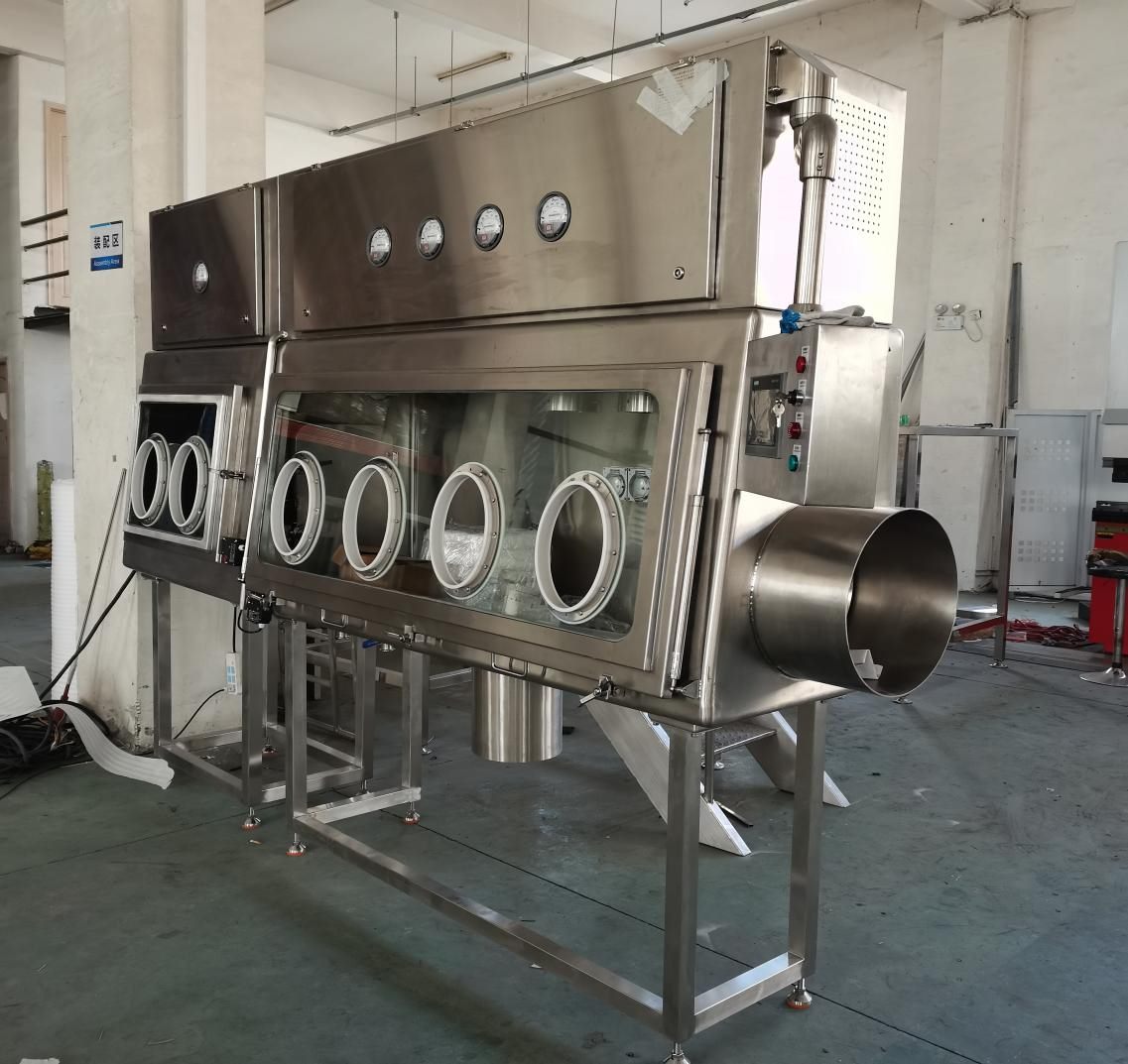
Fenggu builds charging isolators to the reactor and the process rather than as a catalogue item:
- The negative-pressure weighing & dispensing isolator (FG-ISO-DP) is designed for weighing, dispensing and charging of API powders. It is designed for OEB5 (OEL 0.01 mg/m³, SMEPAC test), runs an automatic pressure-decay leak test with a report, uses push-push filter change, and can be fitted with RTP or split-valve connections, nitrogen protection, an integrated scale, WIP and continuous bag-out.
- The negative-pressure containment isolator (FG-ISO-CN) runs at −50 to −80 Pa, is designed for OEB5, meets ISO 10648-2 tightness and can be built in an explosion-proof version.
- Both can be single- or double-sided, with the number of gloves and the overall size made to your layout.
FAQ
What is a reactor charging isolator?
A negative-pressure glovebox mounted on a reactor manway or charging nozzle, in which bags and containers are opened and emptied so that potent or hazardous powder enters the reactor without exposing the operator or the room.
What is an MDS isolator?
The name is used in some catalogues for isolators used in material dispensing and reactor charging. In function it is the same equipment: a containment isolator with a discharge connection to the process vessel.
Can the isolator stay connected to the reactor during the reaction?
Only behind a closed isolation valve. The isolator is not a pressure vessel and should never see reactor pressure or vapour.
Does a charging isolator need nitrogen?
When flammable solvent is present in the reactor or the powder is combustible, yes — usually nitrogen inerting with oxygen monitoring, together with grounding and explosion-proof electrics.
What containment level can a charging isolator reach?
Well-designed isolators are used for OEB4 and OEB5 compounds. The achieved level must be proven by surrogate testing with real operating steps, not assumed from the design.
Related Products
Dispensing & Containment Isolator (OEB5)Negative-pressure barrier for weighing, charging and sampling HPAPI.Isolators & Barrier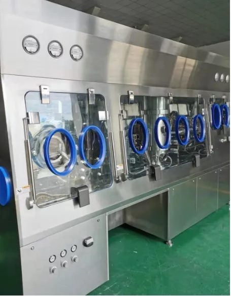 Negative Pressure IsolatorOEB5 containment at controlled negative pressure.Isolators & Barrier
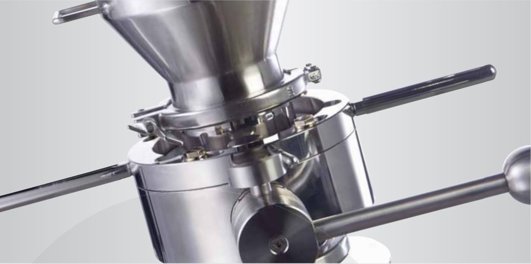 Alpha-Beta Split Butterfly ValveSplit butterfly valve for contained, dust-free transfer of potent powders.Transfer & Containment
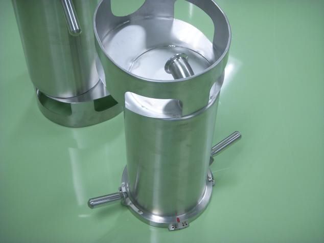 RTP — Rapid Transfer PortRapid transfer port for sterile, contained transfer into isolators.Transfer & Containment
Planning a Contained Charging Step?
Send us the reactor nozzle size, the materials and bag sizes you charge, and whether solvent is present. Fenggu engineers will propose an isolator layout for your reactor.